Quantcast
Channel: Total Phase Blog
Viewing all 704 articles
Browse latest View live

Using a Protocol Analyzer, How Can I View Only the Setup and Data Timing, and Filter Out the NAKs?

$
0
0

Question from the Customer:

I am using the Beagle USB 480 Protocol Analyzer for a full speed USB trace. I want to measure the time between the control transfer and the second IN transfer. Doing that with the cursor shows a delta of 14 ms. However, the trace includes SOFs and polls that add up to over 200ms. The screen shots below the both normal view and the time reference view of a full speed USB trace.

Data Center Software: Full Speed USB Data with Normal View and Time Reference View 
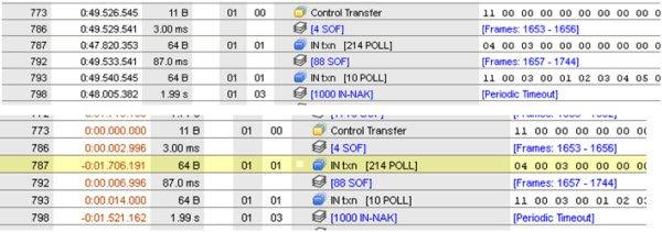
Figure 1: Data Center Software: Full Speed USB Data with Normal View and Time Reference View

How do I get the proper delays displayed in the timing column?

Also, to view only the setup and the data timing, I want to filter out both the SOFs and the NAKs. Using the LiveFilter tab in the Data Center Software, I see I can filter out the SOFs. How do I filter out the NAKs?

Response from Technical Support:

Thanks for your questions! The selected view determines how information is displayed. When you use the class view or the transaction view in the Data Center Software, the records may not be in time-order due to how the data is grouped for higher level parsing. You can see the records in time-order by switching to packet view, which disables the higher level parsing. Note that only the captures run in sequential mode can be viewed in packet view. Following is a summary of the capture views.

Views of Data Capture via Data Center 
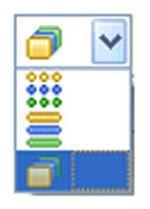
Figure 1: Data Capture Views


  • Packet – Protocol-level decoding is performed - the records are in time-order. Collapsed groups, such as SOFs and IN-NAKs are broken up as necessary to ensure records are in timestamp order. Only captures run in Sequential Mode can be viewed in Packet View. For more information, please refer to section 6.2 of the Data Center Software User Manual.
  • Transaction – Protocol-level decoding is performed - the records may not be in time-order. Collapsed groups are not broken up for time-order preservation. Since there is no time-order restriction, captures generally appear more compact in this view than in Packet View.
  • Class – Class-level parsing is performed -the records may not be in time-order. Captures generally appear high-level and compact in this view. For more information regarding class-level decoding, please refer to section 6.9 of the Data Center User Manual.

For filtering out the NAK packets, go to the LiveFilter tab, click on the Packet radio button under the Protocol section and unselect the NAK checkbox.

Filtering out NAK with LiveFilter Figure 2: Filtering out NAK with LiveFilter

For more information, please refer to the following documents:

We hope this answers your questions. If you have other questions about our protocol analyzers or other Total Phase products, feel free to email us at sales@totalphase.com or submit a request for technical support.


How are CPOL, CPHA and Bitrate Configured for a Host Adapter that is in SPI Slave Mode?

$
0
0

Question from the Customer:

How critical is the bitrate setting in SPI Slave mode? Does the Aardvark I2C/SPI Host Adapter communicate only with other SPI devices that support exactly the clock speeds that the Aardvark does? If not, should the bit rate on the Aardvark be configured higher than that of the SPI master or lower?

Also, the Control Center Serial Software User Manual uses terminology such as rising/falling and sample/setup. How do those terms correlate to CPOL (clock polarity) and CPHA (clock phase), and can you provide more information about that configuration?

Response from Technical Support:

Thanks for your questions! Setting the bitrate applies only to the device in the SPI master mode; it is not necessary to set the bitrate for the device in slave mode, as SPI slave devices use the clock of the master. However, the master and slave devices must agree to the data frame, which is related to the clock transitions, polarity and phase, as indicated in section 4.2 of the Control Center Serial Software User Manual.

Configure SPI Mode via the Control Center Software Serial 
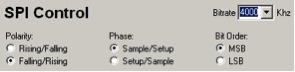
Figure 1: Configure SPI Mode via the Control Center Software Serial

The Aardvark adapter is capable of sending SPI data at 8 MHz, while our newest product, the Promira Serial Platform, with the SPI Active – Level 1 Application, can send data at 12.5 MHz. The Control Center Serial Software can be used with both devices.

Here are the definitions of rising/falling and sample/setup, relative to CPOL and CPHA:

  • rising/falling is equivalent to CPOL = 0; the leading edge of the clock is rising and the trailing edge is falling.
  • falling/rising is equivalent to CPOL = 1; the leading edge of the clock is falling and the trailing edge is rising.
  • sample/setup is equivalent to CPHA = 0; data is sampled on the leading edge of the clock.
  • setup/sample is equivalent to CPHA = 1; data is sampled on the trailing edge of the clock.

Based on those settings, four SPI modes are possible, which are illustrated in Figure 2 below.

The Clock Polarities and Clock Phases affect the SPI Modes Figure 2: Clock Polarities and Clock Phases of SPI Modes

For example, setting the clock polarity to CPOL=0 would configure the SPI to idle the SCLK clock line as low. The clock would then transition low-to-high on the leading edge and high-to-low on the trailing edge.

Similarly, the phase option determines whether to sample or setup on the leading edge. For example, setting the clock phase to CPHA=0 would configure the SPI to sample on the leading edge and to setup on the trailing edge.

For more information about CPOL (clock polarity) and CPHA (clock phase), please refer to section 1.2.3 of the Aardvark I2C/SPI Host Adapter User Manual. For more information about the commands that affect CPOL and CPHA, please refer to section 5.6.2 of the Aardvark I2C/SPI Host Adapter User Manual.

For more details, please refer to the following documents:

We hope this answers your questions. If you have other questions about our host adapters or other Total Phase products, feel free to email us at sales@totalphase.com, or if you already own one of our devices and have a technical question, then please submit a request for technical support.

Using the Aardvark I2C/SPI Host Adapter, How Can I Best Communicate to an I2C Device in Binary Code Format?

$
0
0

Question from the Customer:

I am using the Aardvark I2C/SPI Host Adapter as an I2C master. I am trying to send a read request to an I2C device sensor, which communicates in binary code. Is there a simple way to send a command in the binary format? I am using the Control Center Serial Software GUI, which only seems to accept hexadecimal (hex) inputs.

Response from Technical Support:

Thanks for your question! When using the Aardvark host adapter and Control Center Serial Software, data messages and the load data files can only be done in the hex format. However, other software applications are available - you can read and write I2C/SPI data with the Aardvark host adapter using the Control Center Serial Software, the Flash Center Software  or the Aardvark Software API.  In your case, we recommend using the Aardvark Software API,  which can be customized to interface with specified data formats, including binary.

Aardvark Software SPI Can Be Customized for Multiple Data Formats Figure 1: Aardvark Software SPI - Customize for Multiple Data Formats

Summaries of the key features of the software applications are listed below:

  • The Aardvark Software API is used to control the Aardvark adapter, and to write a custom program for your specific requirements. The API comes with support for multiple operating systems (Windows, Linux and Mac) and multiple languages (C, Python, Visual Basic and C#), and includes software examples. We recommend using the Python bindings as it is a simple language, and is a good option for scripting.
  • The Control Center Serial Software provides full access to all of the Aardvark adapter functionalities, and eliminates the need to write custom software to control the Aardvark adapter. It has also the batch scripting capability when used with the Aardvark XML Batch Script Language.
  • The Flash Center Software provides mechanism to quickly erase, program, and verify I2C and SPI based EEPROM and flash memory Chips. It has an extensible XML parts library with built-in support for EEPROMs and serial flash chips from major manufacturers. Supporting new devices,  we continuously create and add new parts to the library. The Flash Center Software has options to use hex, S-Record or binary data formats, but only for how data is stored; the data formats do not apply to communicating with devices.

For additional information, please refer to the following documents:

We hope this answers your questions. If you have other questions about our host adapters or other Total Phase products, feel free to email us at sales@totalphase.com, or if you already own one of our devices and have a technical question, please submit a request for technical support.

What is the Fastest Time to send I2C Write and Read Operation with a Host Adapter?

$
0
0

Question from the Customer:

I am using the Aardvark IC2/SPI Host Adapter with the Control Center Software in I2C mode. At 400 kHz, I want to send a Write followed by a Repeated Start with a Read. When I observe the I2C traffic, there is a delay of at least 5ms between the Write and the Read. What is the least amount of time that this can occur between an I2C write and read operation? Here is the XML script that I am using:

<aardvark>
<configure i2c="1" spi="0" gpio="1" tpower="0" pullups="1"/>
<i2c_bitrate khz="400"/>
<i2c_write addr="0x12" count="2" radix="16" nostop="1">00 20</i2c_write>
<i2c_read addr="0x12" count="1"/>
</aardvark>

Response from Technical Support:

Thanks for your question! In general, the Aardvark adapter operates at 1 kHz - 800 kHz bitrate as an I2C master or an I2C slave.

Aardvark Host Adapter read-back data can be saved in CSV format. Figure 1: Aardvark I2C/SPI Host Adapter

These bitrates are only achievable within each individual byte and do not extend across bytes. It is not possible to send bytes at a throughput of exactly 1/8 times the bitrate. The I2C protocol requires that 9 bits are sent for every 8 bits of data. The byte throughputs are very close to the theoretical maximum byte throughput of the 1/9 bitrate.  About the delay that you see - there is a finite time required to set up a byte transmission.

The Aardvark adapter also has a 2ms round-trip latency for each Aardvark Software API function, which is caused by the full-speed USB link between your computer and the Aardvark adapter. The GUI and the operating system may add additional delay due to internal overhead, which cannot be changed. So, in conclusion, if you want to create your application, using the API would be your best bet in reducing the delays between write and read transactions. However, if you are simply sending these separate write/read transaction pairs, you can use the Master Register Read command in the Control Center software. This command uses the Aardvark hardware to send the read and write command in succession with almost no delay.

For more information about the I2C signaling characteristics, please refer to section 2.3 of the Aardvark I2C/SPI Host Adapter User Manual.

To meet your speed requirements, we recommend the PromiraTM Serial Platform. The advanced features include operating as an I2C master up to 1 MHz, integrated level shifting from 0.9V to 5.0V. and USB 2.0 / Ethernet connectivity for faster downloads, remote control, and factory floor automation.

Promira Serial Platform offers more features at higher speeds Figure 2: Promira Serial Platform

Regarding speed - the Promira platform supports the I2C master mode at 1 kHz to 1.02 MHz and the I2C slave mode at 1 kHz to 500 kHz. When using USB 2.0 connectivity, the Promira platform uses a high-speed USB link between the Promira platform and the computer, which reduces the USB latency from 2ms to about 250us. The Promira platform has also an API queuing mechanism that may provide additional speed-up for you. For additional information about I2C signaling characteristics, please refer to section 2.2 of the Promira Serial Platform User Manual and to section 5  for details about the Promira Software API. We provide Promira Aardvark Wrapper Software API, which enables you to use the Aardvark API with the Promira platform; however, to maximize the speed of the Promira platform, we recommend using the native Promira API.

We hope this answers your questions. If you have other questions about our host adapters or other Total Phase products, feel free to email us at sales@totalphase.com, or if you already own one of our devices and have a technical question, please submit a request for technical support.


How Do I Set Up Conditional Loops for an SPI Slave with the Aardvark i2C/SPI Host Adapter?

$
0
0

Question from the Customer:

I'm working on a project with the following requirements: the SPI master sends requests the SPI slave every 10ms and the slave responds with the data. For some tests, I may need to add a delay after selecting the SPI slave device. I don't see these options within the Control Center Software that comes with the Aardvark I2C/SPI Host Adapter - I understand that I can use the Aardvark Software API instead.

It would be easiest for me to write programs in LabVIEW – can the Aardvark adapter be used with LabVIEW?

Response from Technical Support:

Thanks for your questions! Yes, the Aardvark adapter can be used with LabVIEW. The Total Phase Aardvark LabVIEW driver is based on the Aardvark API, supports 32-bit Windows and includes example VIs. The Aardvark Software API can also be used to create loops. The API supports a cross platform (Windows, Linux, and Mac OS – 32- and 64-bit) and the following programming languages: C, C#, Python, .NET, VB.NET, and VB6.  Program examples are  provided. We recommend using the Python bindings as it is a simple language and a good option for scripting. Please note - the Aardvark Software API and the Aardvark LabVIEW Driver are offered as two individual packages that are used separately. The Control Center Serial Software does not support conditional loops.

Aardvark LabVIEW Driver Figure 1: Aardvark LabVIEW Driver

For additional information, please refer to the readme files that are provided with the Aardvark LabVIEW Driver package and the knowledge base article Sending SPI Messages Between Two Aardvark adapters Using Aardvark LabVIEW.

Note - as an SPI master, the Cheetah SPI Host Adapter provides user-configurable SPI delays; the Aardvark host adapter does not provide that option. More information about signal characteristics for these host adapters is available in the user manuals:

Additional resources that you may find helpful include the following:

We hope this answers your questions. If you have other questions about our host adapters or other Total Phase products, feel free to email us at sales@totalphase.com, or if you already own one of our devices and have a technical question, please submit a request for technical support.

How Do I Send CAN Messages, Access and Store Data with a CAN Interface?

$
0
0

Question from the Customer:

I am using your Komodo CAN Duo Interface and I see there is a batch script window in the Komodo GUI Software. Is there a way I can use Komodo Software API in that window to send CAN messages, as well as capture and then store data in a file? If so, do you have any API python code examples that I could use?

Response from Technical Support:

Thanks for your questions! The Komodo CAN Solo Interface and the Komodo CAN Duo Interface, used with the Komodo GUI in batch mode, allow you to send messages to the target device; however, this application does not support capturing data. To capture and then store data, you can use the Total Phase Data Center Software. For more information, please refer to section 3.4 of the Komodo GUI User Manual and section 4 of the Data Center Software User Manual.

Note - the Komodo Duo Interface can simultaneously transmit messages and capture data; transmitting messages and capturing data must be done separately with the Komodo Solo Interface.

The Komodo CAN Duo Interface can simultaneously transmit messages and capture data Figure 1: Komodo CAN Duo Interface

The Komodo GUI batch script window is separate from the Komodo Software API. Komodo API python examples can be executed from the command line; they cannot be executed from the Komodo GUI batch mode window.

The Komodo Software API is used to control the Komodo interface and allows you to write custom programs to your specifications. API supports multiple operating systems (Windows, Linux, and Mac) and multiple languages (C, Python, Net, and C#). The following code examples are provided with the API:

  • detect: Detect Komodo devices attached to the system.
  • async: Uses the asynchronous interface to send packets on CAN channel A.
  • gpio: Performs simple GPIO operations with a Komodo interface, including monitoring the pins for voltage changes.
  • loopback: Demonstrates how to open ports, acquire features, write and read data. This example requires CAN channels A and B to be connected together with a properly-terminated cable. (This example only applies to CAN Duo interfaces.)
  • monitor: Monitors CAN bus and GPIO activity. This program prints out timestamps, status messages, errors messages, and data.
  • request: Requests data from specified CAN ID and prints the received data.

Note - the Python API allows you to modify the examples for your system requirements. The examples do not currently include a program that takes data from the received CAN messages and then store that data in a file. For additional information about API, please refer to section 5 of the Komodo CAN Interface User Manual.

More information is available in the following resources:

We hope this answers your questions. If you have other questions about our CAN interfaces or other Total Phase products, feel free to email us at sales@totalphase.com, or if you already own one of our devices and have a technical question, please submit a request for technical support.

What are the Features of the USB Protocol Analyzers that Monitor and Analyze High-Speed USB 2.0?

$
0
0

Question from the Customer:

I am looking for a Protocol Analyzer to monitor and analyze high-speed USB 2.0 devices. Can you describe the features and the differences between the Beagle USB 480 Power Protocol Analyzer - Ultimate Edition and the Beagle USB 5000 v2 Protocol Analyzer - USB 2.0 Edition? Please include how the Beagle USB protocol analyzers and target devices are powered.

Response from Technical Support:

Thanks for your questions! Here are details about both Beagle USB protocol analyzers, and the features that are specific per model:

Both Beagle USB protocol analyzers are non-intrusive USB 2.0 monitors that operate on USB 2.0, work with the Total Phase Data Center Software and provide the following features:

  • Real-time display, search, and filtering of USB data
  • Real-time USB class-level decoding
  • High-speed USB chirp detection and robust automatic speed detection, as well as detect suspend/resume events and unexpected signals.
  • A hardware buffer with a large circular buffer
  • Hardware-based packet suppression
  • Digital inputs and outputs to synchronize with external logic
Beagle 480 Power Protocol Analyzer for Power Measurements and Extended Periods of Data Capture Figure 1: Beagle USB 480 Power Protocol Analyzer-Ultimate Edition

The Beagle USB 480 Power Protocol Analyzer - Ultimate Edition features include:

  • High-speed, Full-speed, and Low-Speed USB 2.0: 480 Mbps, 12 Mbps and 1.5 Mbps
  • VBUS current and voltage measurement
  • Enhanced USB 2.0 advanced triggering

Regarding how this analyzer is powered:

  • Analysis computer supplies the power to the Beagle analyzer over USB
  • Power is passed through the analyzer from the target host port to the target device port

For more information about powering this protocol analyzer and the target device, please refer to section 2.2 of the Beagle Protocol Analyzer User Manual.

Beagle USB Protocol Analyzers support LPM transactions at various speeds Figure 2: Beagle USB 5000 v2 Protocol Analyzer-USB 2.0 Edition

The Beagle USB 5000 v2 Protocol Analyzer - USB 2.0 Edition is meant to be a platform that can be upgraded to USB 3.0 and provides the following:

  • USB 2.0 at the following speeds: 480 Mbps, 12 Mbps and 1.5 Mbps
  • USB 2.0 advanced triggering
  • Field upgradeable to monitor USB 3.0 data

Regarding how this protocol analyzer is powered:

  • An external power supply powers the analyzer, not the analysis computer.
  • Power is passed through the analyzer from the target host port to the target device port

For more information about powering this protocol analyzer and the target device, please refer to section 2.1 of the Beagle Protocol Analyzer User Manual.

Here is a comparison chart for your quick reference:

Figure 3: Comparison Chart Figure 3: Comparison Chart

If needed, you can use the Beagle Software API to create customized programs for your specifications, the following documents may be helpful resources:

We hope this answers your questions. If you have other questions about our host adapters or other Total Phase products, feel free to email us at sales@totalphase.com, or if you already own one of our devices and have a technical question, please submit a request for technical support.

How Can I Make the Cheetah SPI Host Adapter Run Faster When Queuing Data in Smaller Data Blocks?

$
0
0

Question from the Customer:
I am using the Cheetah SPI Host Adapter to send large data blocks at maximum speed. I find that I'm getting reliable SPI transmission for long blocks at 40Mb/sec, which corresponds to 5MB/second - these results are OK.

However, the fastest I can queue data to send using ch_spi_queue_array, in blocks of less than 64KB - since num_bytes is only a U16, is about 1.4MB/second.

What causes this difference in speed, and what can I do to improve the performance for queuing data in smaller data blocks?

About my setup:

  • The laptop is running Windows 7, 64-bit
  • The Cheetah adapter is connected to the laptop via USB.
  • The slave device is an FPGA device. I am only blasting transmit data to the FPGA - I am ignoring what the slave might output on the MISO line.

Response from Technical Support:
Thanks for your question! The difference in speed is related to how data is managed with the Cheetah Software API library and interacting with the operating system, a trait that we cannot change. However, there is a solution to improve the programming speed. For your setup, we recommend using the asynchronous API, which allows you to stream data at higher rates. An example of asynchronous API is provided in the API package: “async”. Examples in C, C#, and Python are available.

Cheetah SPI Host Adapter Figure 1: Cheetah SPI Host Adapter

The key to high performance streaming is to asynchronously submit data to the Cheetah adapter, and then create the next queue while the adapter is shifting out the bytes. Then, before the current queue is completely shifted out, would then submit the next queue for delivery.  Good luck with your application!

Additional resources that you may find helpful include the following:

We hope this answers your question. If you have other questions about our host adapters or other Total Phase products, feel free to email us at sales@totalphase.com, or if you already own one of our devices and have a technical question, please submit a request for technical support.


For More Detailed Analysis when Using the Aardvark I2C/SPI Host Adapter, What External Software Applications Can I Use?

$
0
0

Question from the Customer:

I plan to use the Aardvark I2C/SPI Host Adapter with the external software application Agilent/Keysight VEE. I have installed the Windows driver but cannot detect the adapter in the VEE software. Are there dll libraries that I need to add in system directory or in the VEE installation directory? I see that Total Phase has prepared a driver for LabVIEW which is a similar program.

Response from Technical Support:

Thank for your question! We do our best to support Total Phase customers, but currently, we do not officially support the Agilent VEE development environment. However, Agilent VEE can interface with any standard C DLL. To use VEE, you can use our aardvark.dll and bind to the functions within VEE. To do so, you will need to add the prefix of "c_" to the name of each API function that we have documented. Adding that prefix enables direct access to the API functions in the DLL. For additional information about Aardvark Software API, please refer to section 5 of the Aardvark I2C/SPI Host Adapter User Manual.

Aardvark I2C/SPI Host Adapter Figure 1: Aardvark I2C/SPI Host Adapter

Although we do not have support for VEE, we strive to help as many customers as possible.  We do provide support for LabVIEW and Matlab, two very popular development environments in the embedded systems community.

Additional resources that you may find helpful include the following:

We hope this answers your question. If you have other questions about our host adapters or other Total Phase products, feel free to email us at sales@totalphase.com, or if you already own one of our devices and have a technical question, please submit a request for technical support.

Should I Use the Flash Center Software or the Aardvark API with the Aardvark I2C/SPI Host Adapter to Program the Pages of an I2C EEPROM?

$
0
0

Question from the Customer:
I am using the Aardvark I2C/SPI Host Adapter. For this project, I would like to use Flash Center Software to program the IDT TSE2004GB2B0 I2C EEPROM, which is a 512 byte device that is configured in two 256 byte pages. I have tried to create an XML file to program this I2C device, but can’t figure out how to make it work. Can you help me program this I2C device?

Response from Technical Support:

Thanks for your question! The Flash Center Software supports writing to a number of memory devices. Flash Center Software reads/writes to the first page, which consists of the first 256 bytes of the I2C EEPROM that you are programming.

Flash Center Software can be used with the Aardvark I2C/SPI Host Adapter Figure 1: Flash Center Software

To write to the first page of specific device you are using, please do the following:

  1. Create the part file (the contents of the part file are listed below).
  2. Open the Flash Center Software.
  3. Select Operation | Choose Target...
  4. Select Load Part File...
  5. Select the part file that you created in step 1.
  6. Select "Integrated Device Technology" on the Manufacturer tab and then select "TSE2004GB2B0" on the Part Number tab.

The contents of the XML part file:

<?xml version="1.0" encoding="UTF-8"?>
-<devices>
- <default version="1.0">

<manufacturerName> Integrated Device Technology </manufacturerName>
<maxBitrate> 400 </maxBitrate>
<writeTime> 5000 </writeTime>
<baseDeviceAddress> 0x50 </baseDeviceAddress>
<deviceAlgorithm> I2C EEPROM </deviceAlgorithm>
</default>
-<device version="1.0">
<deviceName> TSE2004GB2B0 </deviceName>
<deviceDescription> DDR4 Temperature Sensor with Integrated 4Kbit EEPROM for Memory Modules </deviceDescription>
<maxBitrate> 1000 </maxBitrate>
<capacity> 256 </capacity>
<addressWidth> 1 </addressWidth>
<writeSize> 16 </writeSize>

</device>
</devices>

However, if you need to write to both pages, we recommend using the Aardvark Software API.  The Flash Center Software is made to be as inclusive as possible, but different chip manufacturers may have custom features on their memory devices that the Flash Center Software cannot access - in this case, writing to separate pages. The Aardvark API can be used to create your own custom applications to read and write to "special" memory chips. You can use the flash and EEPROM examples that are provided with the Aardvark API Software package to customize for your specifications.

Additional resources that you may find helpful include the following:

We hope this answers your questions. If you have other questions about our host adapters or other Total Phase products, feel free to email us at sales@totalphase.com or submit a request for technical support. 

Can I Use Visual Basic with the Aardvark I2C/SPI Host Adapter to Run a Data Exchange with an External Board?

$
0
0

Question from the Customer:

I am looking into purchasing the Aardvark I2C/SPI Host Adapter for computer communication with a microcontroller on an external board for data exchange. I am planning on using a Visual Basic platform to develop an easier customer interface to access the information.

  • Can I use Visual Basic with the Aardvark adapter?
  • Are there program examples available?

Response from Technical Support:

Thanks for your questions! You can write and read I2C and SPI data with the Aardvark adapter using Control Center Software, Flash Center Software, and Aardvark Software API. For your setup, we recommend using the Aardvark Software API, which supports Visual Basic. The Aardvark API gives you access to all the functions of the Aardvark adapter, and you can write a custom program for your specifications. The API comes with support for multiple operating systems (Windows, Linux, and Mac) and multiple programming languages (C, C#, Python, .NET, VB.NET, and VB6 – 32- and 54-bit). Examples programs are provided in the Aardvark API package, which includes the following:

  • aai2c_eeprom - read/write an I2C serial EEPROM
  • aaspi_eeprom - read/write to an SPI serial EEPROM
  • aagpio - run GPIO tests
Aardvark I2C/SPI Host Adapter Figure 1: Aardvark I2C/SPI Host Adapter


For information about the Aardvark API commands, please refer to section 5 of the Aardvark I2C/SPI Host Adapter User Manual.

For more speed and flexibility, you may want to check out our latest I2C/SPI product: the Promira Serial Platform, It offers:

  • Integrated level shifting provides voltages from 0.9 to 3.3 volts without an accessory board.
  • High-speed USB connectivity to the host system provides high performance for benchtop programming, testing, and emulation.
  • Ethernet connectivity is enables remote control for automated operations.
  • Provides 200 mA of power - power your device with easier connectivity.
  • Promira Software API for custom setups and specifications.
Promira Serial Platform Figure 2: Promira Serial Platform

When used with the I2C Active - Level 1 Application, the Promira platform supports high speed I2C programming, high performance debugging, and superior emulation for your I2C protocol needs. I2C programming speeds with the Promira platform are twice as fast as those of the Aardvark adapter.

For the SPI bus, using the SPI Active - Level 1 Application with the Promira platform supports clock speeds of up to 12.5 MHz for master and 8 MHz for slave functionality. Over eight times faster than the Aardvark adapter, the Promira platform supports faster programming for debugging and emulation of SPI devices.

Additional resources that you may find helpful include the following:

We hope this answers your question. If you have other questions about our host adapters or other Total Phase products, feel free to email us at sales@totalphase.com, or if you already own one of our devices and have a technical question, please submit a request for technical support.

Attending DesignCon 2015? Visit Total Phase @ Booth #648

$
0
0

DesignCon2015

DesignCon 2015 in Santa Clara, CA starts on January 27 and the Expo Hall opens on January 28. Total Phase is excited to exhibit this year and thinks there are plenty of reasons you should attend too.

Reasons to Attend

  1. Total Phase is exhibiting in booth #648.  Stop by and talk to our experts about test and measurement for your embedded systems.
  2. Experience the power of the Promira Serial Platform in Live Hands-on Demonstrations.
  3. Learn more about the Total Phase I2C, SPI and USB family of products.
  4. Enter to winPromira Serial Platform.
  5. Registration to the Expo Hall is free.
  6. Happy Hour! Beer and snacks will be served on the Expo Floor on Wednesday and Thursday from 5pm – 6pm.

As technology continues to evolve and move towards the “Internet of Things”, so must the tools to support such a bold endeavor. Total Phase is a leading provider of embedded systems solutions with a commitment to deliver simple, easy-to-use and industry leading test and measurement tools.

Late 2014, Total Phase introduced the Promira Serial Platform, our most advanced serial device ever. Stop by for a short demonstration, to learn about the important new ways Total Phase is keeping up with the changing times and how we have future-proofed the tools you rely on.

Live Presentations: The Power of the Promira Serial Platform will run throughout the day. 

In-booth Demos
Stop by our booth #648 for a demo and see how our complete family of host adapters and protocol analyzers can optimize your time and assist with your project timeline.  Total Phase offers solutions for I2C, SPI, USB and CAN protocols.

Meet the team
Meet the Total Phase team, ask questions and get answers on how your can meet your project goals and deadlines.

*Enter to win a Promira Serial Platform
Stop by the booth, talk to one of our experts and enter to win a Total Phase  Promira Serial Platform with SPI Active - Level 1 and I2C Active - Level 1 applications and one year of support (retail value = $750).  Mention this blog and enter twice.

Winner will be selected at 5:30 on Thursday, January 29 - stop by our booth, see our products and demos, and enter!

Expo Hours
Wednesday, January 28:    12:30pm - 6:00pm
Thursday, January 29:       12:30pm - 6:00pm


How do I Provide Lower Signal Voltage Logic and Power Levels to SPI Target Devices?

$
0
0

Question from the Customer:

I need some help with programing and testing SPI chips on my board. I am using the Aardvark I2C/SPI Host Adapter with the 10-Pin Grabber Clip Split Cable. I am new with the these tools and have some questions:

  • What is the purpose of the NC/+5V line on the cable?
  • The signal levels of my SPI target devices are 2.5V. How does the Aardvark adapter interface with that signal level?

Response from Technical Support:

Thanks for your questions! The NC/+5V line on the 10-pin grabber cable  is be used to deliver the +5V power supply from the Aardvark adapter to the target device.

Pins 4 and 6 (NC/+5V) of the Aardvark adapter can provide +5V power supply to the target system. You can enable these signals by using the following Total Phase software tools:

If you would like to learn more about the SPI pins and signals, please refer to section 2.1.6 of the Aardvark I2C/SPI Host Adapter User Manual.

Aardvark I2C/SPI Host Adapter Figure 1: Aardvark I2C/SPI Host Adapter

For your voltage level question, the Aardvark adapter I2C/SPI signal logic is 3.3V. To adjust that voltage we recommend using the Total Phase Level Shifter Board with the Aardvark adapter. The board  provides I2C/SPI voltage level shifting from 3.3V to  1.2V, 1.5V, 1.8V, 2.5V, and 3.0V, as well as power to the target device.  For information about using the level shifter board, please refer to the knowledge base article Programing I2C EEPROM Using Aardvark Adapter, the Level Shifter Board and the Control Center Serial Software.

Alternatively, you can use our new PromiraTM Serial Platform with the SPI Active - Level 1 Application.  The Promira platform is our latest device for I2C and SPI protocols and has integrated level shifting; there’s no need to connect to an accessory level shifter board.

Promira Serial Platform Figure 2: Promira Serial Platform

The Promira platform supports additional advanced features:

  • Operates as an I2C master up to 1 MHz
  • Provides 200 mA to a power a target
  • USB 2.0 and Ethernet connectivity for faster downloads
  • Operates with SPI devices with the SPI Active - Level 1 Application

For additional information about the Promira platform, please refer to the Promira Serial Platform User Manual.

Additional resources that you may find helpful include the following:

We hope this answers your question. If you have other questions about our host adapters or other Total Phase products, feel free to email us at sales@totalphase.com, or if you already own one of our devices and have a technical question, please submit a request for technical support.

Can I Use and Identify Multiple Aardvark I2C/SPI Host Adapters when Reading and Writing to Multiple I2C and SPI Devices?

$
0
0

Question from the Customer:

I have some questions about using the Aardvark I2C/SPI Host Adapter. I am reading and writing to multiple I2C and SPI devices, and I need to control multiple Aardvark adapters. I am able to find multiple Aardvark adapters under the Windows Device Manager.  What’s the next step?

  • How can I use more than one Aardvark adapter at the same time?
  • Does each adapter have its own address that I can read?
  • So that I know which target device I'm reading, how can I identify which adapter I am looking at?

Note - for another project, I need to use four Aardvark adapters at the same time.

Response from Technical Support:

Thanks for your questions! The Control Center Serial Software can only connect to one Aardvark adapter at a time. If you want to use  the software to communicate with multiple Aardvark adapters, then you need to launch a separate Control Center Serial instance for each Aardvark adapter.

If you ware working with memory devices, you can use the Flash Center Software, With Flash Center, you can connect multiple devices to read and write in parallel; however, the salve devices must be identical. If the devices are different, then you need launch separate instance of Flash Center for each adapter, as in the example above.

Aardvark I2C/SPI Host Adapter Figure 1: Aardvark I2C/SPI Host Adapter

Every Aardvark adapter has a unique serial number, which cannot be changed. You can use the serial number to identify your device. View the serial number in the Control Center Serial Software configuration window, as shown in the figure below.

View Serial Number of an Aardvark I2C/SPI Host Adapter with Control Center Serial Software Figure 2: Serial Number of an Aardvark I2C/SPI Host Adapter

Additional resources that you may find helpful include the following:

We hope this answers your questions. If you have other questions about our host adapters or other Total Phase products, feel free to email us at sales@totalphase.com, or if you already own one of our devices and have a technical question, please submit a request for technical support. 

How Do I Modify XML Files to Use the Cheetah SPI Host Adapter with the Flash Center Software to Continue Production Runs with a New Flash Device?

$
0
0

Question from the Customer:

We use several Cheetah SPI Host Adapters for programming in our production runs and the R&D department. We have been using Atmel AT45DD041D-SSU SPI serial data flash device in our designs. However, Atmel no longer manufactures this device, so we have to change our design. The SPI flash device that we chose is the Adesto Technologies AT45DB041E-SSHN-T. We didn't find it in the Flash Center Software parts list, so we're trying to modify the Atmel XML file to work with this part.

We have used the information in the datasheet to modify the XML files. So far, we haven't made it work for the page sizes we need to use, 256 bytes and 264 bytes - can you help us?

Response from Technical Support:

Thanks for your question! We regularly update the parts files for the Flash Center Software, and a re adding support for new parts all the time. The new devices can be supported by using an existing file of a similar device and then modifying the fields to match your serial data flash device. The fields are located in the device's data sheet, such as device ID and timing parameters. For additional information about using XML files, please refer to section 4.3 of the Flash Center Software User Manual.  To help you get started, we created a beta version of an xml parts file that supports a few Adesto AT45 memory chips:

<devices>
<default version="1.0">
<manufacturerName> Integrated Device Technology </manufacturerName>
<maxBitrate> 400 </maxBitrate>
<writeTime> 5000 </writeTime>
<baseDeviceAddress> 0x50 </baseDeviceAddress>
<deviceAlgorithm> I2C EEPROM </deviceAlgorithm>

</default>
<device version="1.0>

<deviceName> TSE2004GB2B0 </deviceName>
<deviceDescription>
DDR4 Temperature Sensor with Integrated 4Kbit EEPROM for Memory Modules
</deviceDescription>
<maxBitrate> 1000 </maxBitrate>
<capacity> 256 </capacity>
<addressWidth> 1 </addressWidth>
<writeSize> 16 </writeSize>

</device>

To work with your particular page sizes, we recommend the following additions to the XML file above:

  • To use the AT45DB041E XML file with 256 bytes page size, add the field "userTransaction1" with the data "3D 2A 80 A6". This will add the “Power of 2 binary page size (256 bytes): 3D 2A 80 A6" command in the beginning of the operation.
  • To use  the AT45DB041E XML file with 264 bytes page size, add the field "userTransaction1" with the data "3D 2A 80 A7". This will add the “DataFlash page size (264 bytes): 3D 2A 80 A7" command in the beginning of the operation.

For more details, please refer to section 4.3.7 of the Flash Center Software User Manual.

Flash Center Software can be used with the Aardvark I2C/SPI Host Adapter Figure 1: Flash Center Software

The Cheetah adapter and Flash Center software is quite flexible with its expandable parts library so we hope you can use the file above to support any other devices you wish to program in the future.  We hope this answers your question and that your production lines will continue to run smoothly.

Additional resources that you may find helpful include the following:

If you have other questions about our host adapters or other Total Phase products, feel free to email us at sales@totalphase.com, or if you already own one of our devices and have a technical question, please submit a request for technical support.


Using the Aardvark I2C/SPI Host Adapter, How Do I a Perform "Master Register Read" in Batch Mode?

$
0
0

Question from the Customer:

I am using the Aardvark I2C/SPI Host Adapter with the Control Center Serial Software. In the I2C Control section, I see that I can easily perform a "Master Register Read". I observe writes to a device register and then a read with the number of bytes specified in the Number of Data Bytes field. How can I do this in batch mode?

Response from Technical Support:

Thanks for your question! The following information about the Control Center Serial Software read commands may be helpful to you:

  • The Control Center Serial I2C/SPI mode has a "Master Read Register" command that provides I2C write with no stop, and then an I2C read with stop.
    Control Center Serial Software with Master Register Read Figure 1 - Control Center Serial Software with Master Register Read


  • The Control Center Serial Batch mode has "nostop" parameter, write command, and read command. However, the Control Center Serial Batch mode does not have a "Master Read Register" command.
    Control Center Serial Software in Batch Mode Figure 2: Control Center Serial Software in Batch Mode


However, in batch mode, you can implement the register read by using the following two operations:

  1. I2C write with no stop
  2. I2C read with stop

The example below reads four bytes at 100 KHz from the I2C slave address 0x50 register address 08, with the Control Center Serial Software set in Batch Mode:

<aardvark>

<configure i2c="1" spi="1" gpio="0" tpower="1" pullups="1"/>
<i2c_bitrate khz="100"/>
<i2c_write addr="0x50" count="1" radix="16" nostop="1">08</i2c_write>
<i2c_read addr="0x50" count="4"/>

</aardvark>

Additional resources that you may find helpful include the following:

We hope this answers your question. If you have other questions about our host adapters or other Total Phase products, feel free to email us at sales@totalphase.com[RCA3] , or if you already own one of our devices and have a technical question, please submit a request for technical support.

Did You Know You Can Use the Komodo Can Duo Interface with CAN High Level Protocols?

$
0
0

Question from the Customer:

I am new to CAN, and I have some basic questions. Does the Komodo CAN Duo Interface support running as a Host? I have a device with a Dual CAN interface that runs as a Slave/Client. I would like to test this device with a tool that can run as both CAN Master and Host for TPDO and RPDO with periodic delivery.

Also, can the Komodo interface function as a master for a CANOpen slave device?

Response from Technical Support:

Thanks for your questions! The Komodo CAN Duo Interface is a two-channel USB-to-CAN adapter and analyzer. The Komodo interface is capable of active CAN data transmission as well as non-intrusive CAN bus monitoring. The Komodo interface has a transfer rate up to 1 Mbps and includes eight configurable GPIOs. You can use the Komodo interface with the Komodo GUI Software or the Komodo API Software.

 Komodo CAN Duo Interface Figure 1: Komodo CAN Duo Interface

The flexible Komodo API allows you to interface with CAN high level protocols and to create a custom program that supports your requirements, such as being able to work with CANOpen.

The Komodo API comes with support for multiple operating systems (Windows, Linux, and Mac), multiple programming languages (C, Python, Visual Basic, and C#), and includes programming examples. For more information about the API, please refer to section 5 of the Komodo CAN Interface User Manual.

Additional resources that you may find helpful include:

We hope this answers your question. If you have other questions about our host adapters or other Total Phase products, feel free to email us at sales@totalphase.com, or if you already own one of our devices and have a technical question, please submit a request for technical support.

How Do I Configure an Aardvark I2C/SPI Host Adapter or a Promira Serial Platform for CRC and an SPI Slave Device with Flag Signals?

$
0
0

Question from the Customer:
I am interested in your host adapters, the Aardvark I2C/SPI Host Adapter and the PromiraTM Serial Platform, and I have a few questions about how they handle SPI. My SPI application has two flag lines back from the spi slave device. I want to use an SPI tool, such as the Aardvark adapter or the Promira platform, to simulate the master. here are my questions:

  • How do I configure the GPIO pins on the (master) tool for the "flag lines"?
  • How is CRC (cyclic redundancy check) handled – is it through the device or software?

Response from Technical Support:

Thank for your questions!


Promira Serial Platform Figure 1: Promira Serial Platform


Aardvark I2C/SPI Host Adapter Figure 2: Aardvark I2C/SPI Host Adapter

In SPI mode, both the Promira platform and the Aardvark adapter have two GPIO signals that can be configured using the software GUIs or the API.

CRCs are not handled by the hardware, but can be supported  via the APIs. The Software APIs support multiple OS (Windows, Linux, and Mac) and multiple languages (C, Python, Visual Basic, and C#), and include examples. We recommend using the Python bindings, which is a simple language and an effective option for scripting.

Additional resources that you may find helpful include the following:

We hope this answers your question. If you have other questions about our host adapters or other Total Phase products, feel free to email us at sales@totalphase.com, or if you already own one of our devices and have a technical question, please submit a request for technical support.

Did You Know You Can Shift I2C or SPI Logic Signal Levels without a Level Shifter Board?

$
0
0

Question from the Customer:

I am trying to use the Aardvark I2C/SPI Host Adapter or the Cheetah SPI Host Adapter to program an SPI chip that uses 1.8V as the high logic level. Do the Aardvark or Cheetah adapters support various logic signal levels?

Response from Technical Support:

Thanks for your question! We have two solutions for programming a device with a 1.8V logic level:

  • Use the Level Shifter Board with the Aardvark and Cheetah adapters
  • Use the integrated level-shifting feature of the PromiraTM Serial Platform (no accessory boards are required).

The Level Shifter Board

Level Shifter Board Figure 1: Level Shifter Board

Following is a summary of the Level Shifter Board features:

  • Level shifting for I2C, SPI, and MDIO signals
  • Supports voltage levels of 1.2V, 1.5V, 1.8V, 2.5V, 3.0V, and 3.3V
  • Supply power to downstream devices
  • I2C speeds of 800 kHz
  • SPI and MDIO speeds of 20 MHz

The Promira Serial Platform

Promira Serial Platform Figure 2: Promira Serial Platform

The Promira Serial Platform is a robust tool that has the functional flexibility of licensed applications. What are currently available are the SPI Active - Level 1 Application and the I2C Active - Level 1 Application. New, more robust applications will be made available. One of the current features is the level shifting from 0.9V to 5.0V, which applies for both SPI and I2C signals. Following is a summary of the advanced features of the Promira platform:

  • Integrated level shifting from 0.9V to 5.0V
  • USB 2.0 and Ethernet connectivity for faster downloads, remote control, and factory floor automation
  • I2C up to 1 MHz
  • SPI up to 12.5 MHz for master and 8 MHz for slave

Additional resources that you may find helpful include the following:

We hope this answers your question. If you have other questions about our host adapters or other Total Phase products, feel free to email us at sales@totalphase.com, or if you already own one of our devices and have a technical question, please submit a request for technical support.

How Can I Set Up the I2C/SPI Host Adapter for Synchronous I2C Reads from Two Separate I2C-to-CEC Translators?

$
0
0

Question from the Customer:

We are using the Aardvark I2C/SPI Host Adapter and the GPIO to test our prototype I2C-to-CEC Translators. These prototype boards are connected together, and each one is connected to an I2C master. The first board receives a few bytes over I2C (the first Aardvark adapter writes the data) and translates them to CEC format. The second board receives the CEC encoded byte stream and translates it back to an I2C stream (the second Aardvark reads the data).

The first board receives the I2C bytes correctly. Our difficulty is reading the I2C bytes from the second board, as we do not know exactly when the I2C data is available in the second board. We use batch mode I2C reads with delays, but we miss many I2C bytes.

How can we use I2C reads without missing any data from the second Board? How can we synchronize I2C reads when the data is generated on the second board?

More details about the setup:

  • The delay between the time that the first I2C-to-CEC Translator reads the I2C data from the first Aardvark adapter until the second I2C-to-CEC Translator is ready to send the I2C data to the second Aardvark adapter is 120 milliseconds.
  • The delay for the first translation cycle is 124.5 milliseconds, followed by a delay of 120 milliseconds for the following translation cycles.
  • The second I2C-to-CEC Translator has an LED that indicates when it is ready to send the I2C data to the second Aardvark adapter.
  • The I2C in both translators are interrupt driven. The main Processor sets up the I2C slave with the data buffers to be received or sent on I2C (first and second translators respectively) and proceeds to run other tasks. When the I2C master on the Aardvark adapter provides the clock, the data gets written or read, respectively.

Response from Technical Support:

Thanks for your question! The Aardvark adapter is definitely the right device for what you are trying to accomplish. With its I2C master capabilities and four GPIO signals, and the flexible and customizable Aardvark Software API, you can make sure that all the data is being read by using the GPIO lines on the second Aardvark adapter to synchronize with the second I2C-to-CEC board.

Aardvark I2C/SPI Host Adapter Figure 1: Aardvark I2C/SPI Host Adapter

Here are the guidelines for synchronous I2C reads:

  • Connect a GPIO signal from the second Aardvark adapter to the hardware of the indication signal in the second I2C-to-CEC Translator.
  • When the second I2C-to-CEC Translator is ready to send the I2C data to the second Aardvark adapter. If the I2C-to-CEC Translator can generate a hardware signal indicator to the second Aardvark adapter, then you can write program using the Aardvark API to generate the read operation to the second Aardvark adapter for reading data from the second I2C-to-CEC Translator.

Alternatively, the PromiraTM Serial Platform, would be an ideal tool to support your system requirements with even more capabilities. Compared to the Aardvark adapter, it has shorter USB and Ethernet delays between it and the host computer.

Promira Serial Platform Figure 2: Promira Serial Platform

A summary of the Promira platform features:

  • I2C master up to 1 MHz
  • A shorter delay between the host computer and the I2C adapter via USB or Ethernet
  • Integrated level shifting from 0.9V to 3.3V

The current release of the Promira platform supports I2C Active – Level 1 and SPI Active – Level 1 Applications. More features will be available as we release more software applications to drive the Promira platform.

Additional resources that you may find helpful include the following:

We hope this answers your question. If you have other questions about our host adapters or other Total Phase products, feel free to email us at sales@totalphase.com, or if you already own one of our devices and have a technical question, please submit a request for technical support.

Viewing all 704 articles
Browse latest View live